
UPPSALA
Technology
Two questions decide whether a high-rate clarifier performs: does the floc stay in suspension, and does the water take the path the designer intended. A deep-bed denitrification filter turns on a third: does every part of the bed see the same flow of water and air.
High-rate clarification
Keeping the floc in suspension
This applies to every configuration — plain, sand-ballasted and magnetite-ballasted alike. Two things decide it: the impeller, and the draft-tube system around it.
The impeller
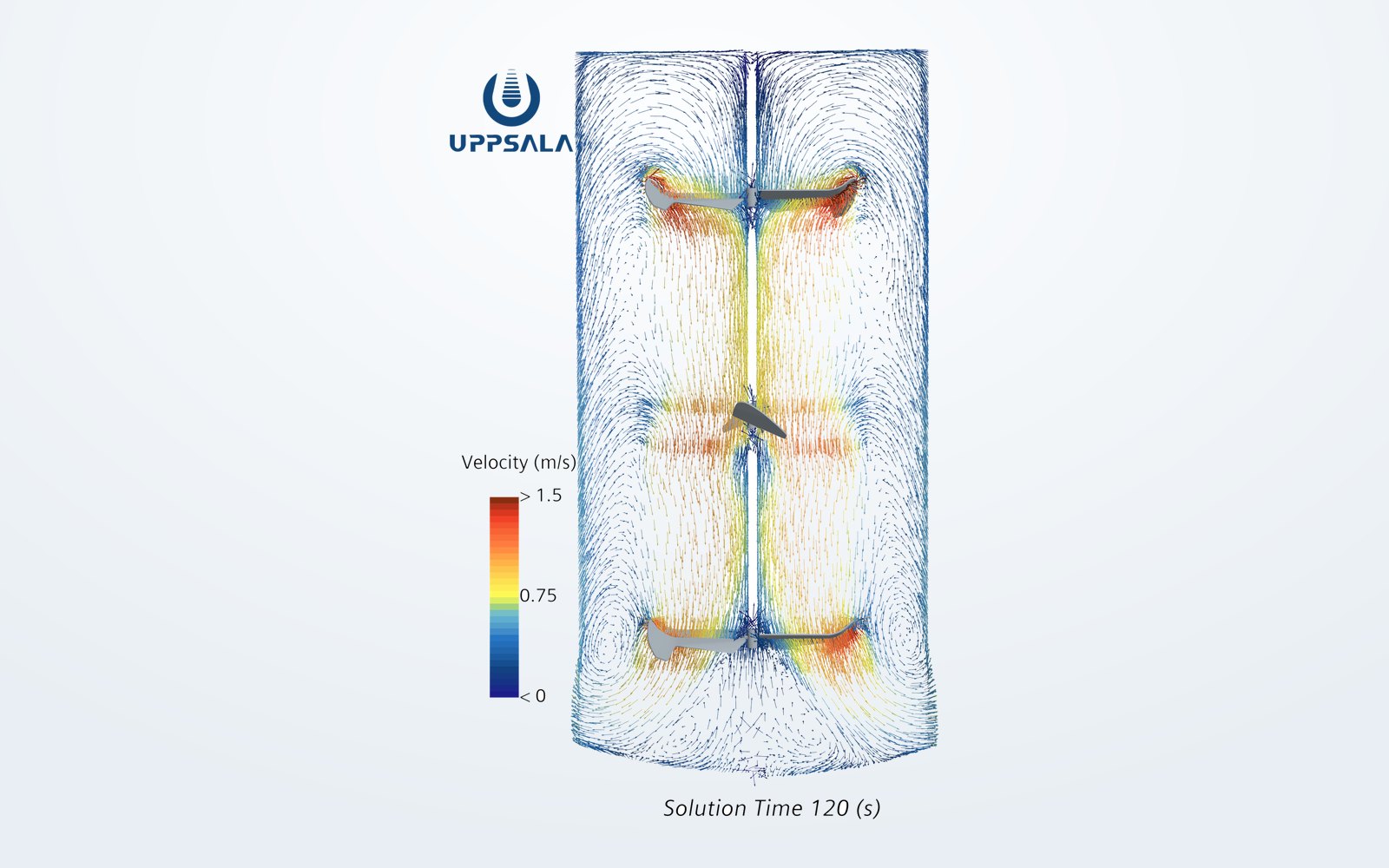
We design our own blade geometry rather than fitting a general-purpose agitator. Each of the four profiles targets a specific duty, and multi-level arrangements can produce a vertical circulation pattern that acts like a draft tube without one being installed.
Where ordinary blades fail
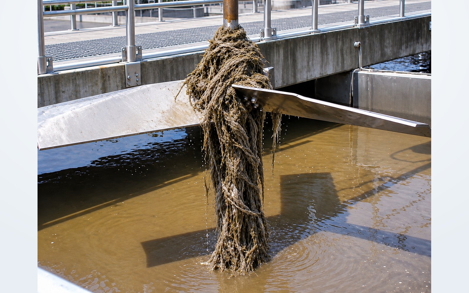
Municipal wastewater carries hair, fibre and textile. On a conventional blade these wrap around the hub and accumulate until the impeller stops pumping. The UPP ARH-3 swept-back hydrofoil lets that material slide outward along the blade and off the tip.
The draft-tube system
The draft-tube arrangement changes what the same impeller can deliver. Two transient CFD runs of the same duty, one with a draft-tube system sized for the tank and one with a conventional arrangement, differ by 16% in flow number once both have settled.
- Custom draft-tube system
- Conventional draft-tube system
Data table
| Time (s) | Custom draft-tube system | Conventional draft-tube system |
|---|---|---|
| 0 | 0.035 | 0.034 |
| 20 | 0.364 | 0.300 |
| 40 | 0.383 | 0.310 |
| 80 | 0.625 | 0.518 |
| 180 | 0.629 | 0.543 |
Flow number Nq is dimensionless: pumped flow divided by impeller speed and the cube of impeller diameter. It measures how much liquid the impeller moves for a given size and speed, so it can be compared across cases.
What that means in the tank
Particle volume fraction for the two arrangements. With the custom draft-tube system the solids are carried up into the body of the tank; with the conventional arrangement they collect in a lower recirculating zone.
Custom draft-tube system
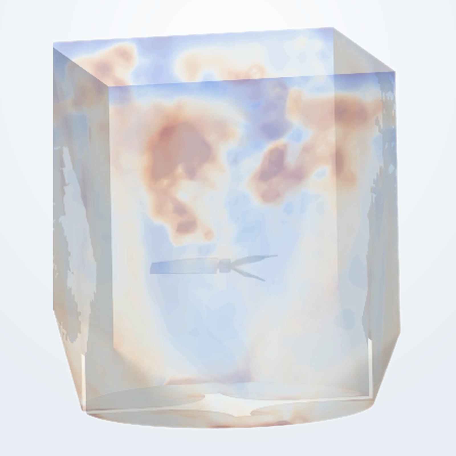
Conventional draft-tube system

Conditioning the hydraulics
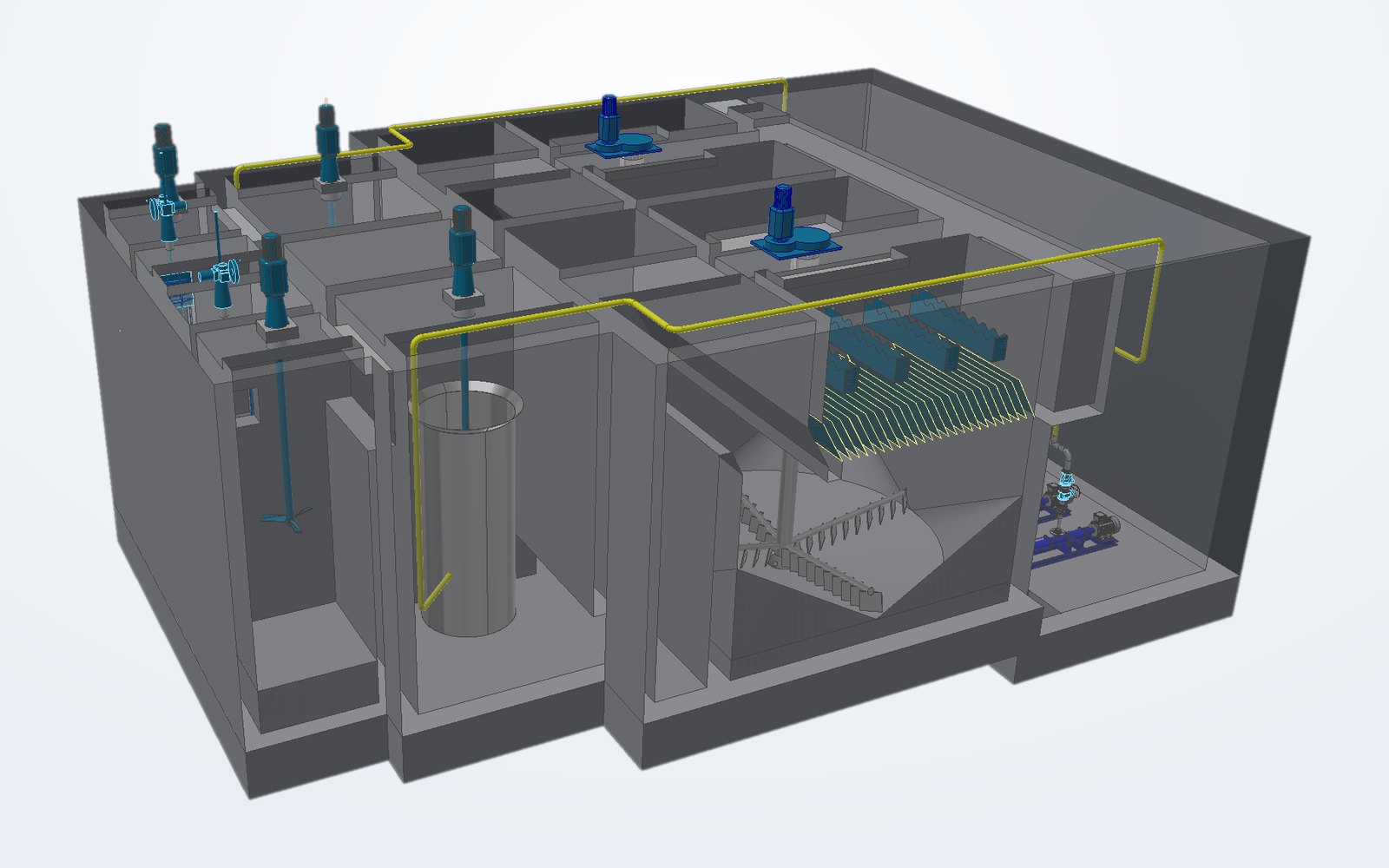
Conventional practice assumes that taking water in at the bottom and out at the top — or the reverse — is enough to avoid short-circuiting. It is not. We build a flow-guiding arrangement for each project to stretch the real effective retention time and give the coagulant and flocculant the contact they need.
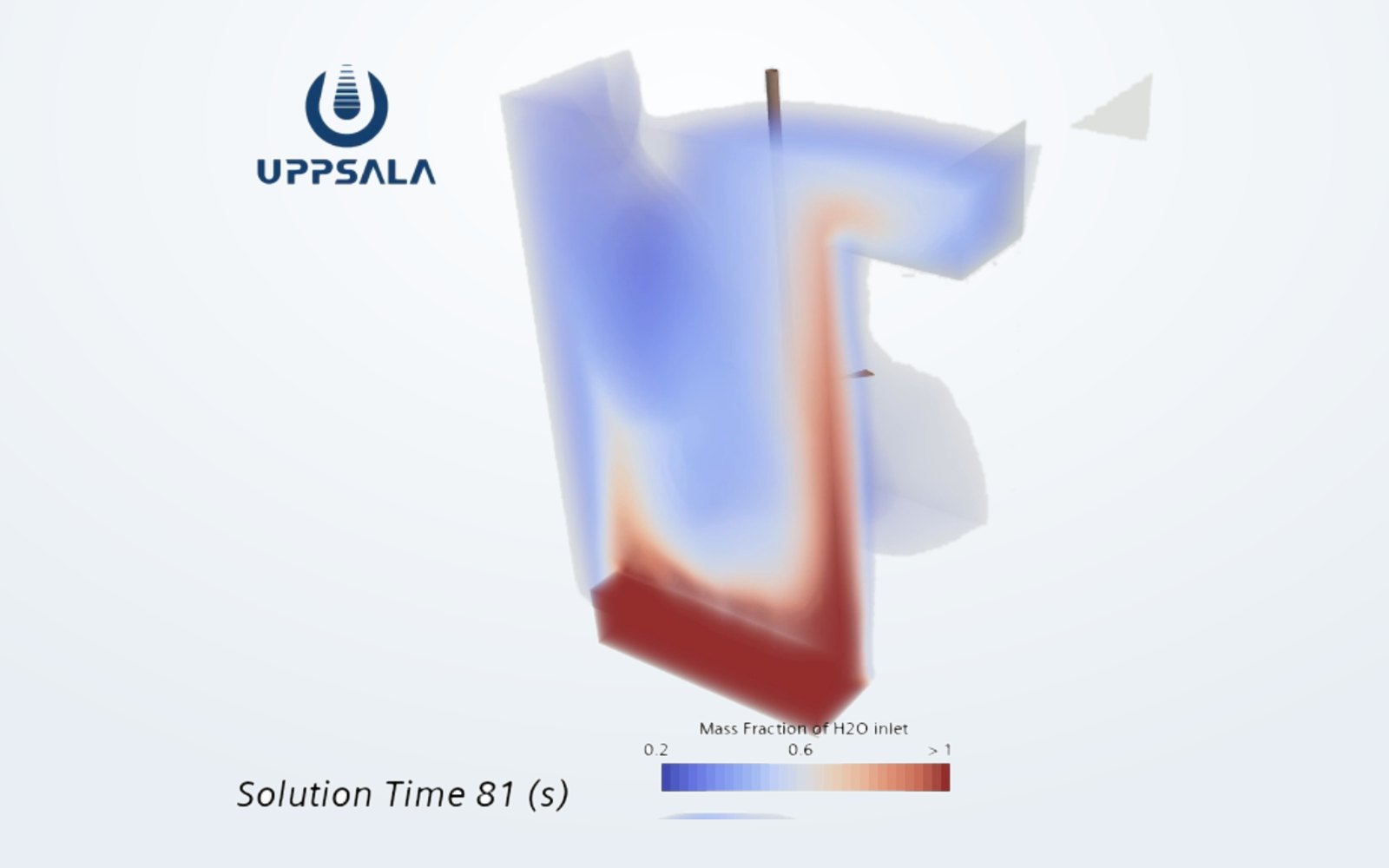
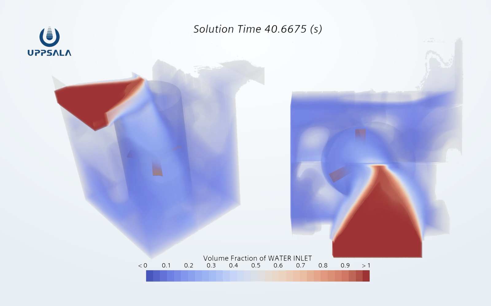
These are two separate studies, on different tank geometries and with the tracer released at different times, so they are not a controlled before-and-after of one tank. Each shows the flow pattern of its own case.
Deep-bed denitrification filtration
Every design decision in a deep-bed filter rests on one thing: whether water and air are distributed evenly across the bed. Where they are not, part of the bed is overloaded while another part does nothing, and backwash never fully recovers it. We reworked the conventional distribution arrangement.
Before

After

Process arrangement
- 1 Constant level operation
- 2 Headloss rises
- 3 Air scour
- 4 Air + water backwash
- 5 Water backwash
- ↻ back into service